Station View software package (Software Technical verification No. 205466)
It’s a tool for collecting and managing the information of measuring stations, with notification and alert.
Specifications:
1. It is designed on an integrated geographic database and is applicable.

2. It is under network and server support of time series, images and maps
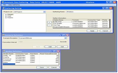
A. Data gathering subset
3. Stores information received from stations in the database within the defined time series.
4. Calculates and updates the larger time interval of defined parameter for the defined object in geographic database, such as calculating daily information from hourly information.
5. Defines and stores a channel to communicate with stations through GSM modem using DATA-SMS-GPRS, PSTN modem, radio modem, modems for satellite systems and directly.
6. Defines and uses multiple communication channels simultaneously, and to allocate automatically available channels to communicate with the station, based on the priority defined for being in waiting list to use the communication channel of receiving information.
7. Defines and stores different time intervals of contact and receiving station information in different scenarios and ease of switching scenarios at different times.
8. Defines and stores the way of collecting information of station in two ways: the center will automatically call the station, or the station calls the center (on regular basis and at the time of event).
9. Supports various types of data logger and common RTU devices on market, such as the list below and the ability to support and add new devices, if there would be required documents.
AANDERAA, SOLINST, THIES, SEBA, THEODOR FRIEDRICHS, OTT, FISHER, LAMBERCHT
10. Reports and stores all the statuses to the communication channel of the station, including the completion of receiving, busy source line, inaccessibility, loss of defined port, in case the modem and device is off, the remaining time to the next call and being in waiting list of communication channel.
11. An automated process management system, to leave unpredicted stop situations, in each communication stage.
12. Design and implementation of software based on multi-threaded technology to increase the speed of operation and optimal use of system capabilities.
13. Simultaneous implementation of several scenarios on several computers to reduce contact traffic during a crisis.
14. Defines the continuity of attempt to communicate with the station based on priorities and limits in waiting list for using the communication channel.
15. Supports received information via SMS and GPRS for loggers that have the possibility.
B) The subset of data calculation
16. Calculating statistical summary of collected data for a longer time interval, such as calculating hourly information from collected minute information and calculating daily information from hourly information, and the ability to choose the beginning and ending time.
17. Analytical and intermediate calculations of new parameters based on the received information and storing them in water resources database in same time interval and longer time interval, like evaporation from water tank of automatic stations and calculating the river flow based on the readings of water level, using conventional methods.
18. Identifying data of outside of permitted numeric range, and inserting a separation flag for data (error, read, calculated)

19. Sets the sequence of auto-computing time.
20. Pre-defines computational functions such as aggregate, average, minimum, maximum and differential.
21. Reports the status of the calculated and entered records in the water resources database..
22. Comparison with previous data in inserting time and deciding to insert new data.
C- Sub-set of real-time panel
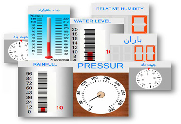
23. Defines and stores the way of displaying information received from stations and stored in the database with a mechanical device view (Mercury-round gage thermometer) and a schematic of industrial equipment on large monitors and LCDs.
24. Defines and stores arrangement of the way of displaying measured parameters of several stations in one page.
25. Runs multiple schematic views and displays on large LCD screens for monitoring and crisis management rooms.
D- Subset of Alarm Management Panel
26. Message management and adjustment program based on numerical modifications of all of the time series stored in the water resources database, including information collected from stations with the following capability
27. Defines and saves the category of message recipients in different groups in terms of organization and priority.
28. Defines and saves messages in a fixed, dynamic and combined format for messages of the type SMS, Email and the alert window on monitor screen.

29. Defines and saves processing and threshold module (micro) in VBA, for stored time series parameters related to Objects that are defined in the database.
30. Sets and monitors the implementation of modules defined in the system with different time intervals.
31. Runs multiple simultaneous processes in the system and creates different messages based on the defined contact groups.
32. Creates different dynamic messages based on the results of implemented modules performed for each contact defined in the system.
33. Defines and saves management reports from the status of the notification and alert system of recipients, to the system administrator.
34. Dynamic WEB support for users to access data over the Internet.
E- Subset of MAP BASE MONITORING
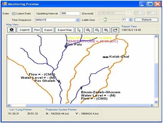
35. Defines and saves dynamic map report of time series information, with different colors on the display to use in monitoring and crisis management rooms, with the feature of map browsers in geographic information systems.
36- ZOOM and PAN feature
The following subsystems form the main components of the station view software:
1. Defines and saves the type of data logger or RTU installed in sections associated with the database objects with necessary information to contact the station.
2. Defines and saves the connection of fields which are related to the database objects, to the data channels of Data Logger or RTU installed in the measurement station.
3. Defines and saves active communication channels in the system
4. Defines and saves scenarios for sequence of contact to the stations
5. Automatic reception program for information of stations and status display
6. Display of the information received and stored in the database in form of schematic and measuring devices.
7. Defines and saves communication channels for sending messages
8. Defines and saves recipients' profile, categorized recipients' and sent messages
9. Defines and saves the process and threshold module to generate messages.
10. Implementation program for modules and sending message
11. Displays information received and stored in database, in numerical and chart form, in mapping environments
